


Jake L
-
Posts
349 -
Joined
-
Last visited
-
Days Won
8
Content Type
Profiles
Forums
Downloads
Store
eMastercam Wiki
Blogs
Gallery
Events
Posts posted by Jake L
-
-
On 8/11/2023 at 2:50 PM, Jobnt said:
I'm projecting 12,000 entities onto some surfaces.
12,000!?!?

@Jobnt I know you talk about having a ton of entities in your files, so I'm curious, what industry do you make parts for?
We do a lot of aerospace parts and my bigger files have a couple thousand entities total, seems like your totals must be in the tens if not hundreds of thousands

-
A lot of solutions come to mind. Simplest way I can think of is a 3D Flowline toolpath
-
 1
1
-
-
3 hours ago, sharles said:
You guys who do programming for high-volume machining are in a completely different place than I am... where I'm in a mold and pattern shop and everything is one-off and so speeding and pushing things aren't a huge factor for us. I'm afraid if I ever left my company or they closed down(which is a constant fear because of how many of our competitors have closed over the years and how few quality guys we have left at our company), I'd be completely worthless trying to do what you guys do because it's a totally different mindset. It's a little frustrating after nearly 30 years to realize I'd have very few employment opportunities outside the little niche I'm in...
I see both sides where I am. Sometimes it's 2000 pcs and sometimes it's 1. While it's true we look at jobs differently depending on qty, the initial goal is always to make a good part. It's better to make good parts slowly, than scrap parts quickly.
-
5
-
-
I also feel your pain. If there is a way to get rid of this step around the edges I'm all ears. As far as I'm concerned these cuts around the edges of the part just waste time and wear out the tool.
My understanding is this happens when you tell MC to leave stock on the floor and the walls. I'm having trouble figuring out how to explain it, but the way I think about it is MC doesn't realize it should also be leaving stock on the edge of the part. It sees the surfaces and as long as it is leaving the correct amount of stock relative to each surface, if there's still stock left, it will try to chase it. Though I could be way off in my thought process.
Here's another thread that may help: EMC Post
-
If you have an existing post you should be able to find (closer to the end) where other parameters are called in from Mastercam.
Looks to me like you have to define a table with "fprmtbl"
Also need to define a variable to set the parameter value to.
Then in the post you should be able to use the variable you defined to incorporate whatever logic you may need.
That's the best explanation I have. I'm sure someone else will have a fuller explanation as I'm a post editing newb. Hope it helps!
-
2
-
-
Thanks for the response James!
Here's what I figured out:
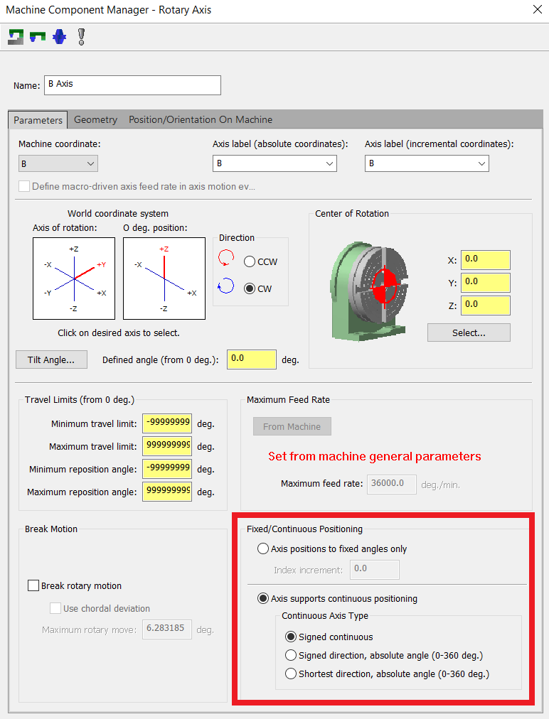
1. "Axis positions to fixed angles only" this one seems pretty self explanatory. If you want the axis to only ever increment by a fixed amount, this is the right option. For example, 5° 10° 15° etc.
2. "signed continuous" this one is for if you want the rotary axis to be signed (negative or positive) and the output can be greater than 360.
3. "signed direction, absolute angle (0-360 deg)" this one is for if you want the rotary to only output a number between 0 and 360. The rotary gcode will also have a sign on it. For example, B-7 or B190.
4. "shortest direction, absolute angle (0-360 deg)" this one also keeps the rotary output between 0 and 360. instead of a signed output, it will output an M code to tell the rotary which direction to turn for shortest distance.
I don't fully understand the difference between option #2 and #3. Is it just that #3 won't output a number greater than 360? Because I have option #2 selected and I have yet to see a rotary output greater than 360. Please let me know if I got any of this information incorrect, I'm eager to learn. I'm still fairly new to post editing and don't do it nearly often enough.
I appreciate any tips and tricks. I do know I'm supposed to make a post backup, and a backup of my backup, and then back that up. That seems to be the most common tip.
-
I'm gonna drag this old thread to the top to ask the question again. I just setup a custom ribbon and was disappointed to see all the icons different sizes. I'm guessing there still isn't a fix for this?
If that is the case, my next question is, are yall still using the quick access toolbar for a custom "ribbon"? Or is there a better way in the newer versions?
-
31 minutes ago, Aaron Eberhard said:
Absolutely. Once you get the hang of using Unified, you'll find yourself using it for everything. Can't get one of the 3 axis paths to give you a good blend? Unified. Can't get a decent undercut toolpath on your 3 axis part? Unified.
It's like Frank's Red Hot. I put that on EVERYTHING.
This.
100% THIS.
I cannot believe how versatile Unified is.
-
1
-
-
I'm back updating what was originally an MPFAN post for our H.Plus-630 HMC. I've made a lot of updates up to this point and am looking for something to be explained to me. I sifted through this forum for a while but didn't find a good explanation.
My question is, in the "Fixed / Continuous Positioning" box on the machine rotary axis page, what should I have checked? Currently my settings are as shown in the screenshot. I have "force_index" set to yes in the post, but I'm not sure if that's how it should be setup.
On the machine the B-axis is a full rotary which is setup to rollover so it does not need to unwind. Would it make more sense to turn on "Axis positions to fixed angles only" in the MD and have the index increment set to .001? (this is the smallest B move the machine can make) Or should I leave the MD the way it is?
We don't do much 4-axis simultaneous work, but I'd like the MD and post to be setup for it if we need it. I also find myself using the unified toolpath more and more, so I want to make sure the MD and post can handle this as well.
I can post snippets of the post if it's needed. Please let me know if more info is needed. MC2023 working in Code Expert 2023. Thanks in advance for any information.

-
You may be better off creating a solid with your model carved out of it then programming it the "normal" way. You can accomplish this by using the Solids > Create > Impression tool.
Another option is to create surfaces on the model you have and flip the normals. Surfaces > Create > Surfaces from Solids --- then --- Surfaces > Normals > Change.
I'm sure there's other ways as well, just a couple off the top of my head, many ways to skin a cat in Mastercam.
Once you have the "inverse" of your model, the 3D toolpaths will function a lot better for you.
-
58 minutes ago, TacoMachinist said:
Anyone having an issue with 2024 just adding random tools when making toolpaths?
In previous versions if I only had 1 tool in my tool list it would just default to that tool. but now its just adding a random tool that I don't know the source of?
For example: I was just starting roughing and only had a 1/2 endmill with a 1" flute length (the only 1/2 endmill in my library). Next operation and skip the tool page since there's only 1 tool and it added a 1/2 endmill with a .5" flute length. this tool doesn't exist in any of my libraries so I have no idea where it came from..
That would annoy me as well.
I'm not on 2024 yet but in 2023 a 1/2" EM with 1/2" flute length is the default tool MC creates if there are no tools in your library and you regenerate a toolpath.
-
Dynamic Transform has always been my go to for repositioning. It seems to make more sense intuitively.
-
On 7/14/2023 at 1:19 PM, Colin Gilchrist said:
The issue is the 'misc values' get reset when you aren't processing a 'Tool Change'.
I did not know this, thanks for sharing Colin!
-
1
-
-
Do you want the two lines of code inserted every time there is a z move? If so, I think you would need to copy your mi4 if statement to right before the G41 cutter comp line.
In the MPFAN post the G41 cutter comp line is in the following postblocks:
prapidout
plinout
pcirout
I believe you'll get what you're looking for if you paste the mi4 if statement right before the cutter comp line.
-
In the solids tab there's a button called "layout" is this what you're looking for? It's very lacking compared to a true cad system, but it may be good enough for your application.
-
1
-
-
2 hours ago, khuongstl said:
The Byte Automatic tool path create, how to I can try ?
On the main page of their website, if you scroll down a tad there is a section about "Free Demo" Thee Byte Website
-
On 7/7/2023 at 2:08 PM, mirek1017 said:
question ,I need to drill over 300 .120 dia holes in SS316 .5 deep .I should spot first ?
I want to use carbide coolant thru drill
Another thing to consider is the tolerances. Are you opening up the hole after drilling, or is the drill finishing the hole? What is the tolerance on the location of the hole?
These are usually the driving questions for whether or not we spot for our drills.
-
On 7/7/2023 at 4:21 PM, Aaron Eberhard said:
A little bit of background info that might help it make more sense: When you generate a toolpath, all pages viewed/parameters changed, and everything it generates creates what's called a checksum (https://en.wikipedia.org/wiki/Checksum ).
If you haven't visited a page (in this case it sounds like the coolant page), the toolpath will be written with whatever is the programmatic defaults are. When you open the parameters and view the page, the checksums can get altered because a page in the dialog changed. In a case like coolant, it shouldn't matter, of course, but each exception has to be managed.
Please make sure to send the file into Mastercam so they can make sure that coolant page updates don't get flagged in whatever situation your file is in.
Just want to say a formal thank you for frequently taking time out of your day to share your knowledge Aaron!
Mastercam's code structure is interesting to me, and I've never heard of checksums.
The more I learn about the code behind the beast, the easier it is to understand why things work the way they do. Thanks again!
-
3
-
-
13 hours ago, neurosis said:
Back when I started in the trade, everything was text and you had just enough info to set the job up. It's almost to the point now where you need a video of someone setting up and running the job.
A couple of my more skilled coworkers say that 20-30 years ago (at the same shop we're at now) they used to get handed a sticky note with a list of tools on it. They would run whole jobs with just a sticky note.
I can't imagine scribbling a few tools on a sticky note and not drawing up a whole packet of OP sheets.
-
2
-
 1
1
-
-
15 hours ago, Jobnt said:
Levels should also have an option to show contents when active and hide it when inactive. This so you can arrow-key through the levels and find what geometry you're looking for, just like the Ops Manager has the option to turn on toolpaths for the selected operation so you can arrow-key through that and see toolpaths turn on and off. Makes finding stuff easier.
If you go into the levels manager, in the settings, and check on "Only active level is visible" and "Arrow keys set active level" and leave everything else unchecked, I think you can accomplish what you're looking for?
-
1
-
-
On 6/27/2023 at 8:02 AM, sharles said:
we stuck with the custom Excel sheet we use to give our operators toolpath information
We do a lot of aerospace and defense industry parts. Sometimes the customer needs 1 part and sometimes they need 1,000. We have a pretty good mix of different quantities.
We have a tool sheet that looks very similar to your first image which has all the tooling information on it. Each custom tool is an additional sheet to show what the tool is. 1-2 sheets for setup (x / y / z zeros) which are screenshots or "print to pdf's" of solids and notes drawn inside Mastercam. Add a handful of inspection sheets (print to pdf's again) and a couple screenshots of the part after it has run through verify, and that's what our guys get to run each OP.
As far as I know we've never looked into automating our tool sheet generation, but it isn't a bad idea. I'm sure it would save a lot of us a lot of time.
-
There was a forum thread a while back about this, though I think it was on the official forums.
If I remember correctly, the response was that there is no way to change the chain order. Model chamfer automatically chooses the chain order regardless of the order defined in the chain manager.
-
1
-
-
This video walks you through turning on PWE. This must be enabled to change parameters.
https://www.youtube.com/watch?v=XEELHseoX5E
I'd recommend writing down anything you change in case you want to change it back in the future. We keep track of all our parameter changes right in the machine parameter manual.
-
1
-
-
We have a Fanuc 16i control and the parameter# is 5101.0 (FXY)
0 = always Z-axis
1 = specified axis (G17 / G18 / G19)
The wording in our book is:
"The drilling axis in the drilling canned cycle is:
0 : Always the Z-axis
1 : The axis selected by the program"
The parameter is in the manual with the other canned cycle g-code parameters.
Mouse vs Trackball
in Industrial Forum
Posted
Just ordered one of these. Never used a trackball before but I'm always looking for ways to program more efficiently. Plus, amazon has a free return policy, so I figured if I hate it I'll just send it back.
I like the looks of that CADMouse as well, might have to order one of those and try it out for a couple weeks too.
I tried using a 3D connexion Space Explorer for a while. I hated moving my hand back and forth between the number keys and the mouse, so I ditched it and got used to the standard mouse camera controls. I currently run a dell MS116 (aka not fancy or special at all).