


Jake L
-
Posts
349 -
Joined
-
Last visited
-
Days Won
8
Content Type
Profiles
Forums
Downloads
Store
eMastercam Wiki
Blogs
Gallery
Events
Posts posted by Jake L
-
-
Have you run canned cycles in G18 / G19 mode before?
I believe the machines are typically defaulted to only allow canned cycles in G17 mode.
There's a parameter you need to flip to change this. If you need it, I'll see if I can dig it up in my notes.
-
Here's your file back. Morph_Trial_JakeL.Mcam
I turned on a second check group (Parameters > Collision Control > Checkbox above big 2). Then you can uncheck "avoidance geometry" in #1 check group. In the #2 group, in the avoidance geometries, select just the two wall surfaces. Then if you uncheck machining geometries it allows you to input a number into the "stock to leave" field. You'll also have to check the "flute" box in check group #2.
Hope this helps!
-
Alright here goes my explanation:
When a G2 / G3 code is called there are a handful of values the machine cares about.
1. The start point, or the x, y values the machine is currently at before starting the G2 / G3 line of code
2. The end point, or the x, y values on the G2 / G3 line
3. The center point of the arc, or the i and j values on the G2 / G3 line. This is a little more complicated because the i and j values are offset values. For example if you start at x = 1.0 y = 1.0 and i = 0 j = -1.0 then the center point would be (x + i , y + j). In this example that means your center point would be (1.0 + 0 , 1.0 + (-1.0)) or (1.0 , 0).
4. Finally the arc radius can be calculated from the #1 start point and #3 center point. In the example above the radius of the arc would be 1.0
For a G2 / G3 line to execute, the #2 endpoint must lie on the #4 radius.
If we use the example above, the code would look something like this:
N100 G01 X1.0 Y1.0
N101 G02 X2.0 Y0.0 I0.0 J-1.0
This code would execute properly because the point X = 2.0 Y = 0.0 does fall on the defined radius (a rad with radius = 1.0 and center point at (1.0 , 0)).
Now if we alter the code a bit:
N100 G01 X1.0 Y1.0
N101 G02 X3.0 Y0.0 I0.0 J-1.0
With the new endpoint x value being x = 3.0, the end point is no longer on the defined radius.
This is what is causing your machine to alarm out. The machine does the necessary computations (finding the #3 center point and #4 radius) and then tries to go to the #2 endpoint and realizes the endpoint does not fall on the defined radius.
-
 2
2
-
 4
4
-
-
2 minutes ago, mcpgmr said:
That's correct. The example I've given was written by hand. What I'm looking for is a method to get the same output or result from Productivity +.
Got it, that makes a lot more sense. I won't be much help in that case. Have a nice day!
-
It looks like on the N108 line you have a bad number.
If you don't have a good understanding how the G2 / G3 code works I'd recommend looking into that. If I tried to explain it it would just sound like gibberish.
Regardless, if you do out the math (or use a CAD software) the N108 line will not compute out correctly. Basically you are asking the machine to make an impossible move. I can try to give a better explanation if you want but that's the gist of your issue.
-
Unfortunately I've never used Productivity+ so I can't help you there. But unless I'm misunderstanding the question, I think you have everything you need.
It sounds like what you're looking for is how to figure the depth the csink tool should go to. Correct?
6 hours ago, mcpgmr said:G98 G82 Z[#601-.17] R5.1289 F6.79 P3000
If I'm reading this correctly, it looks like your Z value is the value stored in #601 minus .17. So this code should machine a Ø.405 csink.
To change the csink dia just change the .17 value to the depth you want the csink tool to go below the surface.
-
1 hour ago, Colin Gilchrist said:
If you love the math, Mastercam Post Processors use Vector and Matrix Math (Linear Algebra), to derive all the rotary angle output for 4-Axis and 5-Axis. If you look at the NCI Data (raw toolpath motion) from a 4-Axis or 5-Axis Program, there are no Rotary Angles output in the NCI Data. All angles are resolved inside the Post Processor, from "vector inputs". For a 4-Axis Program, the Tool Plane Z-Axis Vector, is compared to the WCS Z-Axis Vector, using the 'atan2' function. For Toolplane processing, this is done 'automatically' inside MP.DLL (the Post Engine), which then sets the internal Rotary Variable 'c$'. (No matter if you are outputting "A" or "B" or "C" for the Rotary, the internal variable is named 'c$'.)
If you want to learn about editing Mastercam Post Processors, check out the link in my signature...
I have dabbled in post editing, mostly just reordering, adding, or deleting certain codes. I've never gone into the math of it, mostly because I haven't needed to. Someday I'll have an excuse to dig into the math, and I'm sure it'll be frustrating and make no sense... I'll love it.

Thanks for all this information!
-
1
-
-
6 hours ago, byte said:
//let;s make a shared pointer to a cstring because yolo lol
lol
-
1 minute ago, neurosis said:
You don't really need a hole axis. Just use wireframe and create a line normal to a point, select the surface (solid face) and a point. You can put the point anywhere and still figure everything out.
I swear it is baffling how many new things I learn on this forum, thank you.
2 minutes ago, neurosis said:Before we had T/S I had to figure out how to do this in MC without the math. We were doing this a LOT and my math skills leave a lot to be desired.

We rarely do this, but knowing how is a very important tool in my toolbox for when we do need it.
I love the math behind all this stuff. Not saying I want to do all this out by hand all the time, but little problems like this break up the repetitiveness nicely.
-
2
-
-
8 minutes ago, neurosis said:
I don't know if this is what you're looking for
Read through that and see if it is.
It's certainly not an easy button but it works to get the rotation if you're trying to mill (or drill) a compound angle and you're stuck on a vertical machine with only a one axis tilt table.
That is exactly what I was looking for, thank you!
I never thought about using hole axis to get the angles, but that does the trick on my actual part. That absolutely is an easy button compared to doing out the math.
As for the sample file, there was no holes in the solid model.
This idea is untested, but I think I could load in a 5 axis machine, create a surfacing op, and set the tool axis perpendicular to the angled face. Then if I post that operation it should give me the two rotation angles.
-
2 minutes ago, So not a Guru said:
Are you looking for bisect line?
Thanks for the reply.
I have used bisect line in the past, but I don't think it would be useful in this situation. Unless I'm completely overlooking something, which is entirely possible. -
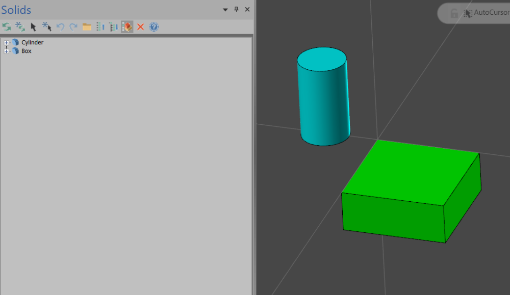
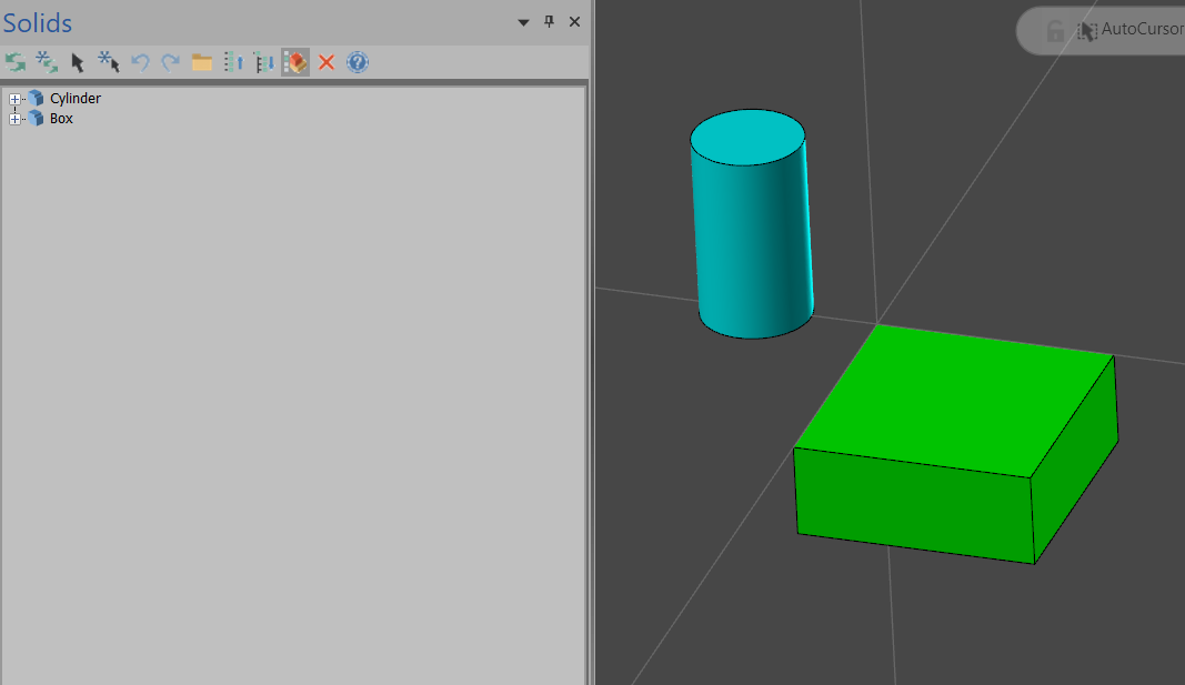
4 hours ago, Tariq Aslam said:
is there some way to distinguish between the 2 solids as they are both named Solids and it becomes difficult to call them for getting their geometries. I am trying to get geometries from both solids using NET HOOK API
Not exactly sure of the precise question here but...
In the solids manager you can rename any existing solids by either slow double clicking the name, or right click > rename. When you hover over the solids in the solids manager, if the solid is visible in the CAD view, it should be highlighted (this depends on your config settings). To display the solids manager View > Managers > Solids.
In regards to doing this in a Net Hook, I am more familiar with CHooks than Net Hooks. But I imagine the solid name (as described above) is stored with the solid entity in the database. I imagine the name is retrievable and editable from inside the Net Hook. Though this might one of those CHook-only situations.
-
1
-
-
I'm looking for a button in Mastercam, I'm not sure whether or not it exists. If this button doesn't exist, then I'm looking for recommendations on easier ways to do this.
Here's a link to a sample Mastercam file, my math notes, and a couple helpful screenshots: Dropbox Link
What I'm trying to do is find the two angles that make up a "double angled face". I can do the math out to get the angles (see pic above), but this feels like a huge waste of time. Is there a button in MC that will do this for me?
I understand how to use the dynamic transform and align surfaces, but in this case I need the actual number of degrees for each rotation. I also understand there will be more than one solution to the proposed question. I am looking for the angles when rotated around the Top plan Y axis, then rotated around the Top plane X axis.
If an "easy" button doesn't exist for this, can anyone recommend an easier way than what I showed? I'll probably end up making some kind of excel "calculator" for this situation.
Please let me know if anymore information is needed. Thanks in advance. MC2023
-
22 hours ago, Aaron Eberhard said:
Finding the tools is the easiest part, knowing they exist is the hardest.
This is so true.
When I was first learning Mastercam (2020) I would spend hours drawing a few pieces of wireframe or something, just to learn there's a button that can do it in one click.

-
As always, a sample file would be very helpful here.
This is how I would setup the transform toolpath to achieve something like the picture.
Transform Toolpath Parameters 1
Transform Toolpath Parameters 2
22 minutes ago, Accurpress said:Is what I'm wanting to do even possible? To select one toolpath geometry then be able to select multiple areas within the part that aren't neatly arranged along a linear line?
As far as I know the geometry you are trying to machine will have to be equally spaced. The spacing can be in a line like you said, or a grid. It looks like you're trying to use point to point, I'd recommend trying "rectangular" as shown in pic 2.
26 minutes ago, Accurpress said:If someone could point me to a video or pdf I'd be grateful.
Honestly I don't know of any great resources for learning the transform toolpath. I learned with trial and error. The help center is sometimes very helpful and sometimes way too vague (little blue question mark at bottom right of the Mcam parameters window).
You also may need to edit your post to output subprograms to you're liking. Hope this helps!
-
On 4/28/2023 at 8:14 PM, SlaveCam said:
Just wanted to clarify that M9 is output after each Advanced Drill operation using the same tool, not after each hole.
Just found this issue for myself.
If you post this file Advanced_Drill_Coolant_Issue the code is as shown:
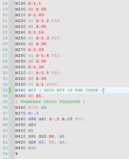
Luckily the post I was using turned the coolant back on before drilling the next hole. But using the MPFAN post as shown, the next hole is drilled with no coolant.
This is MC2023, we haven't downloaded 24 yet. If I can get on the official forum I'll throw a post there too.
-
On 6/2/2023 at 4:12 PM, ajmer said:
this might explain things
Thank you ajmer! That was an incredibly helpful video.
On 6/3/2023 at 9:29 AM, crazy^millman said:In your example if i wanted an even amount of stock across that face for a finish operation for a mold surface I would come in leave finish stock cutting with a semi finish operation. Each of the scallops left from opti-rough leave places where tool pressure will not be even. That will translate back to the finish surface even with a flat endmill. A lot of people forgot even the biggest diameter Carbide tool has deflection.
That makes a lot of sense, and it isn't something I had thought about. Luckily, in this situation the toolpaths in the sample file are for a rough operation. In the future this will definitely be in the back of my head.
The couple example stories you gave were mind boggling. I can't imagine seeing a 1/4 endmill bend over like that. And I never would of thought a shaft that size would have that much movement, honestly I wouldn't have expected any movement at that scale.
Here is another copy of the original file with the "solution" to my question Mcam File . I added a second machining geometry group for the non-flat faces and input .050 for stock to leave on both floor and walls. This is also my first time using Dropbox so please let me know if I did something wrong.
Thanks again for the replies!
-
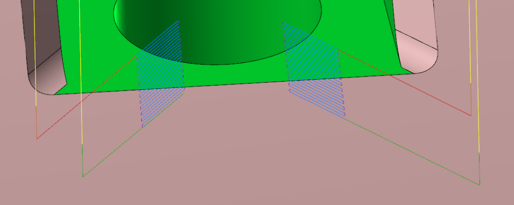
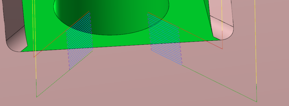
This one's tough to explain so please check out the sample file. Basically in a 3D OptiRough toolpath, when leaving a different amount of stock on the face vs the walls the tool doesn't seem to respect both values when milling an angled surface. I think I'm misunderstanding this, unless there's a magic button I don't know about?
The OptiRough toolpath in the file leaves .050 on floors and .020 on walls. What I would expect is something like this:
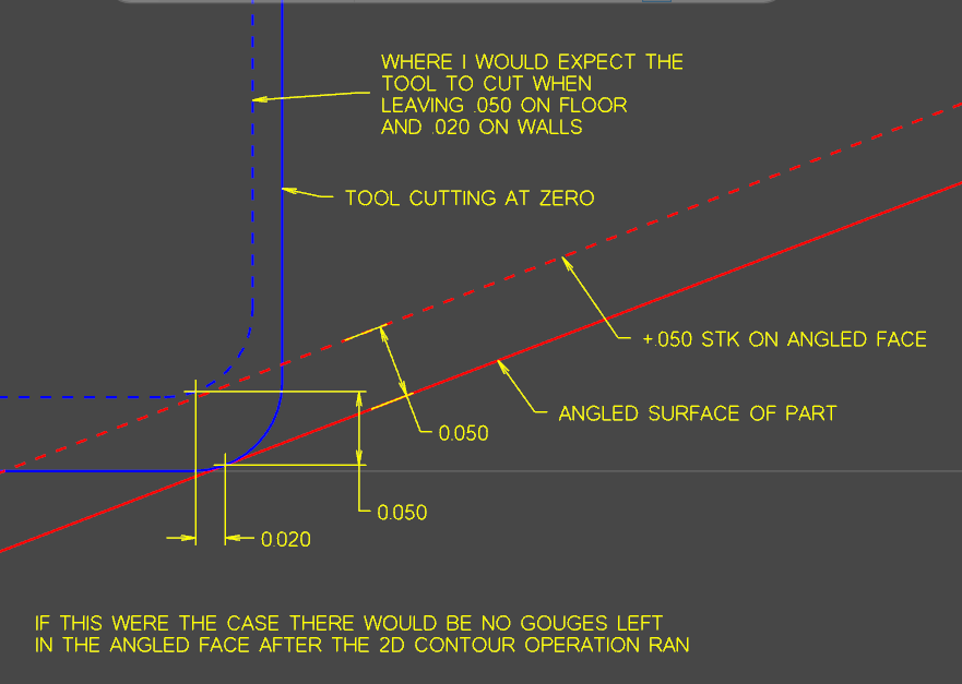
Meaning, if I were to rotate the part and cut the angled face with the end of an end mill (as shown in picture after verify picture), I would not have any marks left behind from the OptiRough operation. However, when I create a stock model or run the two toolpaths thru verify, I get this:
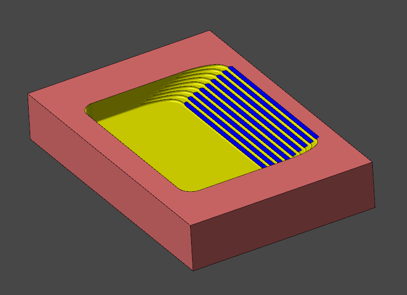
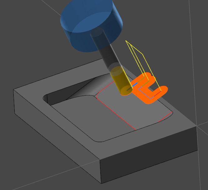
In conclusion, what am I doing wrong here? If I want the OptiRough operation to leave enough stock so the 2D contour operation to clean the whole face, what do I need to do? Thanks in advance for any information anyone can provide. MC2023
-
Thanks for all the information. Manual entry it is
-
Thanks for the quick replies.
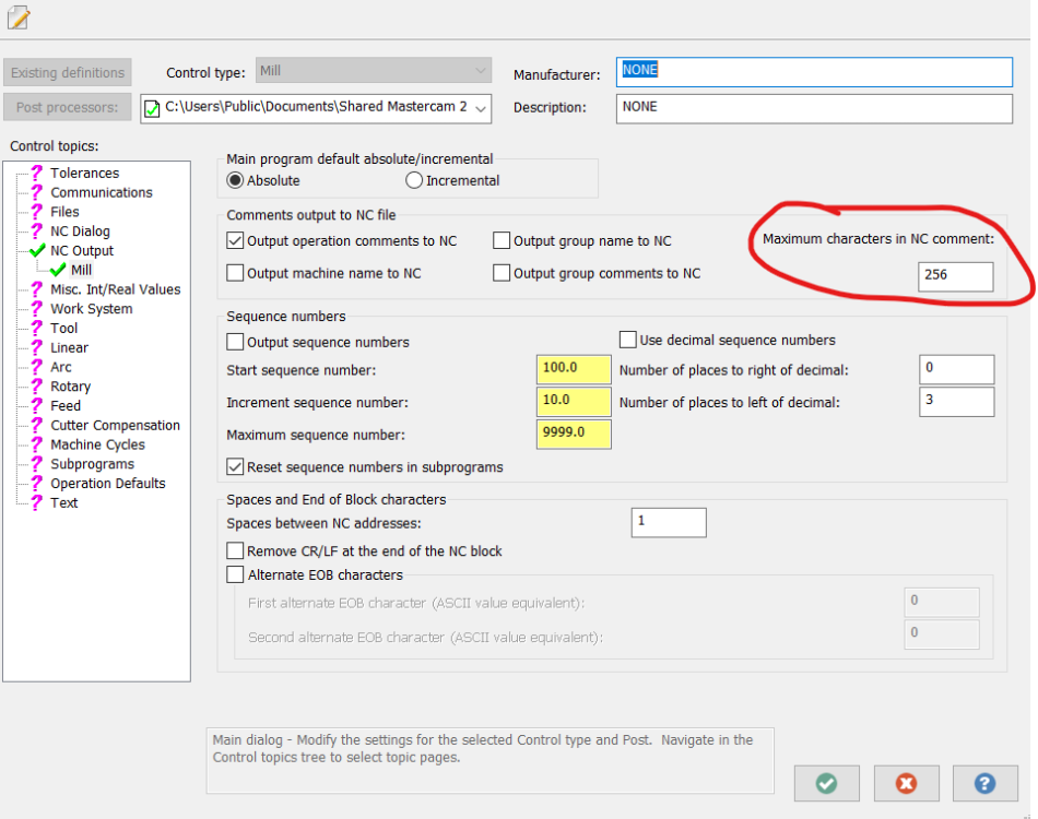
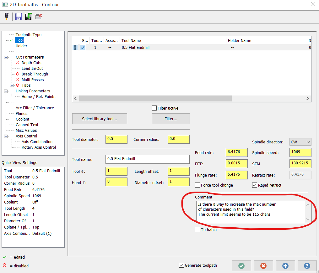
I just realized this wasn't the setting I was looking for. Is there a way to increase the max number of characters allowed in the Comment section of a toolpath?

-
Is there any reason not to increase this value in the CD from 256 to 512, or even bigger? Will it slow down the software, or the posting? MC2023 TIA
-
19 hours ago, rgrin said:
Trying to figure out other ways to machine these largish chamfers. I can make a multiaxis morph work well enough but was just curious what other options I have
I have to say a quick thank you here. I always knew using Morph in the Unified toolpath was possible, but I never knew how to use it. I never thought to add two curve fields as shown in your sample file. Thanks!
-
1
-
-
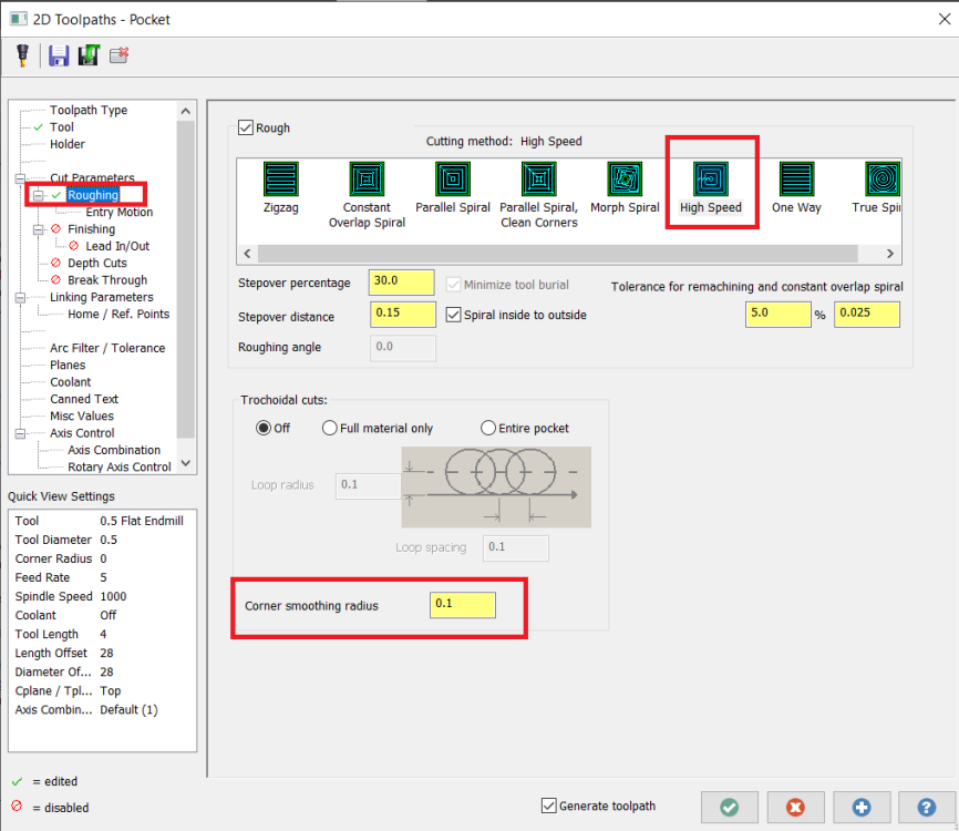
I agree with what Aaron said above.
In a 2D pocket toolpath, using the "high speed" method gives you the "corner smoothing radius" option. I believe this gives the same behavior you're looking for but also limits you to only one cutting method.
-
Thanks for the replies!
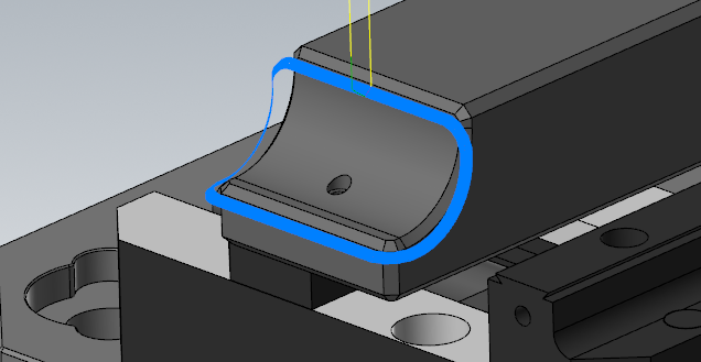
49 minutes ago, Colin Gilchrist said:I couldn't do it with a single path. Here is the result with two paths.
I was trying to stick to a single path because on the actual part there's 32 of these little pockets, all at slightly different angles / depths. I was hoping I wasn't going to have to tediously go through every toolpath for every pocket to make custom adjustments. I thought I wasn't understanding how the start point control worked.
52 minutes ago, Colin Gilchrist said:First, I created edge curves, and built new Net Surfaces.
Genuinely curious here, why did you do this? Is it more accurate? I used "surfaces from solids" and trimmed the surface.
54 minutes ago, Colin Gilchrist said:Then I changed the type to "full, start/end at exact edges". This give you the "Margins" Page. This you can use to adjust how "close" the tool machines to the edge.
Learned something new today, thanks!
52 minutes ago, crazy^millman said:Change your step over. The amount of step over just happen to fall into that spot. Try a .001greater or smaller amount and go from there.
I tried this and the best I could do was fix 3 out of 4 of the leads.
Sometimes I got 3 bad leads.
Ron and Colin, thanks again for taking the time to look at this for me. It looks like my best options is to have two separate toolpaths for each pocket. I guess sometimes there's no easy button.


Where can I download Mastercam X4?
in Educational Forum
Posted
Is there anyway this is a miscommunication and the original post means MC2024?
X4 = 24 ... Maybe?