


JB7280
-
Posts
1,008 -
Joined
-
Last visited
-
Days Won
9
Content Type
Profiles
Forums
Downloads
Store
eMastercam Wiki
Blogs
Gallery
Events
Posts posted by JB7280
-
-
3 hours ago, JParis said:
That's just letting you know that somewhere on the geometry there is a negative drafted face.....opti-rough can't undercut so it's just an alert
I'm not sure I follow. It alerts you by slamming the tool through the part? Or are you getting different results when you run it?
-
Can anyone tell me what I'm missing here? When I choose "detect undercut stock" the whole thing goes haywire.
I know the holder, and speeds and feeds aren't right. Ignore that.
Operation 20 is the toolpath in question.
https://drive.google.com/file/d/1HGUEcak81AX10rDAywKfnzjKNCpoDuKg/view?usp=drive_link
-
9 minutes ago, Jake L said:
I've not heard a good solution to this issue. Programming the tool as a sharp corner is a very interesting solution.
I suppose it'd be possible to modify the model to make a "plus stock" model and run opti rough off that. Depending on your part that could be a LOT of extra work.
If someone has a better way to eliminate these cuts I'd love to hear it.
From looking at the generated stock model, it appears to have eliminated those cuts. I might not use that approach on something like inconel, or carpenter, but on aluminum, I'm not worried about the little bit of extra material.
-
I noticed I always have lots of wasted cuts in optirough, particularly on top corners. I'm guessing because technically, there is more than whatever stock you left, and it goes around the corner to trim that off.
It looks like, by lying and saying my tool has a sharp corner, I can eliminate these extra passes. This particular part is 6061. I understand that it'll leave extra material, and my be an issue on tougher materials. But, as long as I account for that, it shouldn't cause me any problems, should it?
Or is there a better way?
-
19 hours ago, crazy^millman said:
You mean the we want to make your life harder to use the software function with no ability at start up to turn it off?
I was going to ask this question. I hate that button, and always forget to turn it off. There's no way to keep it off by default?
-
On 8/13/2021 at 5:56 PM, crazy^millman said:
I took OP3 and reprogrammed it with tilt lines for the only wireframe and did everything you were doing in 9 operations. Let me know what you think. I did the walls with 2 methods to show you how to do what your were doing with wireframe without needing to draw the wireframe and still get what your were after.
Really confused by the OP3 WCS X Axis not matching the OP3 Index operations X Axis. Why are they 90 degrees to each other? I normally make all of them align to each other, but if it works for you then okay, but through me off a little bit.
I named your operation groups. I also renamed the operations in the those groups so when you post them they all don't post out with the same name. I also added viewsheets to the file to show you how I like to use them to help me communicate setup and other things to customers when I send them files I have programmed for them. Hopefully this is helpful and gives you some idea things you can do with Mastercam.
Have a good weekend.

Link to the file. 5TH AXIS MYSTERY PART OP3
Hey Ron, I was checking out your file, and had a couple questions. When you machined the floors in the pockets, you used a Horizontal toolpath. Any particular reason you use that, versus area mill, or pocket? Just different ways to skin the cat? Or is horizontal better in some way?
Also, when stepping down the pocket like you are, in the swarf and Surface Contour toolpaths, I almost always end up with steps, or ridges on the walls. What's your trick to eliminate that??
Oops....I also just noticed the date on that post


-
22 minutes ago, MIL-TFP-41 said:
I believe you have to play with these settings:
#Primary axis angle description (in machine base terms)
#With nutating (mtype 3-5) the nutating axis must be the XY plane
rotaxis1$ = vecx #Zero
rotdir1$ = vecy #Direction#Secondary axis angle description (in machine base terms)
#With nutating (mtype 3-5) the nutating axis and this plane normal
#are aligned to calculate the secondary angle
rotaxis2$ = vecz #Zero
rotdir2$ = vecx #DirectionThe above settings are for a table that tilts around Y. Depending on which way it tilts you will have to adjust.
Doesn't seem to have changed much. I stripped the file down and left 5 drilling operations so I could upload it. It looks like it's still unsure which axis it's rotating about.
A few issues with the code - the machine needs B90. Not B-90. There's no reason for the second B rotation to B-270. That's why I think it's rotating about the wrong axis. X values should also be X-.614 for all 5 holes, but 2 of them are at x.614.
eMastercam wouldn't let me upload the file. Here's a GDrive link. https://drive.google.com/file/d/1ocXBTjif2RYeo_MT88NYE0TJn62EbNWz/view?usp=sharing
-
1 minute ago, MIL-TFP-41 said:
I believe you have to play with these settings:
#Primary axis angle description (in machine base terms)
#With nutating (mtype 3-5) the nutating axis must be the XY plane
rotaxis1$ = vecx #Zero
rotdir1$ = vecy #Direction#Secondary axis angle description (in machine base terms)
#With nutating (mtype 3-5) the nutating axis and this plane normal
#are aligned to calculate the secondary angle
rotaxis2$ = vecz #Zero
rotdir2$ = -vecx #DirectionThe above settings are for a table that tilts around Y. Depending on which way it tilts you will have to adjust.
Thank you. I'll give it a try.
-
14 minutes ago, Leon82 said:
when i was messing with mine there was a value in the post for axis of rotation but it was older. it mat be in the machine def now
Do you know HOW to do it in the machine def? I'm not too familiar with that side of things. I just use the MD/CD/PST that i'm given usually.
1 minute ago, MIL-TFP-41 said:Are you using the "Generic Fanuc 5X mill" post?
2 minutes ago, MIL-TFP-41 said:Are you using the "Generic Fanuc 5X mill" post?
Yes. I've also tried the Haas VF_TR 5X post
-
I'm programming a part for a VF-4 with a Nikken, 5X indexer. The primary axis rotates about the Y axis. The generic haas post I have, rotates about the X axis. Is there an easy way to rotate this? I'm only doing one part for this machine, so it's not worth it for me to buy a post or anything like that, If I can get around it.
-
I've had this problem, and I believe it was related to tolerance (which I see you already have quite low) and maybe clearance.
-
On 8/14/2023 at 4:02 PM, JHyder2 said:
Can't believe it hasn't been mentioned yet but track balls don't seem popular overall.
I use an Elecom EX-G Pro and love it. Switched several years ago and have never looked back. All the extra buttons are programmed to my most used hot keys and I can easily put my pointer right where I want it (and quickly) with the ball being controlled by my thumb. I have a SpaceMouse on the left of my keyboard and I used to run an auxiliary numberpad on the left as well.
I started having wrist pain from a standard mouse, and the Elecom changed my thoughts on trackballs. Now I switch back and forth every 3-6 months just to prolong the carpal tunnel
-
 1
1
-
-
On 8/14/2023 at 7:58 PM, So not a Guru said:
Yeah, I finally found it on Ingersoll Rand's site. It's not a user friendly site.

Might have been tough because you've been looking at compressors instead of indexable tooling.
(juuuust kidding)
We usually keep a little drawer organizer with about 10-20 of each of the screws for any indexable Ingersoll tooling we have. From what I'm told, those screws actually bend a tiny bit, as part of the design, which is what keeps the insert tucked in the pocket. On most of our High Feed Mills we replace them at routine intervals, otherwise we end up losing screw heads, and inserts during cuts.
-
1
-
-
On 8/1/2023 at 11:02 AM, BSmith23 said:
That looks like what I need, but we just use Active Reports for our set up sheets. Just tried using the shaft as a holder, but then I can't add my normal holder because then it replaces the shaft. I can make the shaft a tool, but I'm not sure it will assemble it. Getting ready to try that now.
Yeah I can't put 2 tools together as an assembly.
In the integrated tool manager, you can right click > edit tool assembly, and build an assembly with multiple holders.
-
18 minutes ago, TFarrell9 said:
Indeed, if your stepup and stepdown are equal, all flats will be cut to the correct stock amounts.
Can you share a sample of this file in question? There are usually at least a couple of solutions for the "weird" things optirough/rest will do by default.
Tomorrow I'll try to recreate it on a different model that I can share.
As far as detecting flats, I have another part, where I used same stepup/down and it didn't seem to pay any attention to the flats rule. There was a large radius on the part that is still wanted to treat as though there were .050" stepups. Parameters set to .300" stepdown, .300" stepup.

-
3 minutes ago, Jobnt said:
I got no solution but I feel your pain. Daily. I don't remember if it was MC back in the day or Gibbs, but there was a Detect Flats feature that would try to ID all the flats in your part and set depth cuts to those. You could also type in your own step depths.
Since most of my parts are not prismatic Opti rough really is tough to get good paths with. I'd love for some insight on how to do this. Now I just create wire geometry and use that.
I learned from a post here, and I also noticed it says the same in the help file, that setting stepup/stepdown the same is supposed to detect flats. But it doesn't seem to work like it should very often.
-
Any time I use an optirough/rest toolpath, it wants to make this little step at the top of the part. It's almost never necessary for the sake of roughing, in my experience, and wasted cutting time. How can I avoid this? I can't share this file, but on this particular tool path, I have stepdown/stepup set the same, to pay attention to just the flats.

-
I'm using a model chamfer toolpath, and it's outputting the lead-in feedrate at the "plunge feedrate" speed. Is there a way to change this?
-
15 hours ago, MIL-TFP-41 said:
What is your experience with the after sales support from that distributor?
Our experience with Methods has been great.
-
16 hours ago, byte said:
wow, awesome, thanks for showing!!
The YBM-8T is a wild machine. I believe methods did a time lapse video of the actual install of our machine. I'll see if I can find it.
Easier than I thought....
-
 3
3
-
-
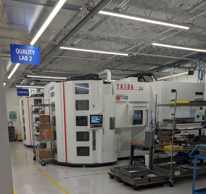
3 hours ago, byte said:
pics or it didnt happen
Here's the PX30i's
-
7
-
-
2 hours ago, Colin Gilchrist said:
Hire Ron to really show you the ropes! Get that PX30i whipped into shape!
We have 2 PX30i's, and a YBM-8T now!
-
 1
1
-
2
-
-
30 minutes ago, byte said:

Who is your Dealer?
I'd rather not. They haven't necessarily done us wrong, so I don't want to put them on blast.
-
1 hour ago, Thad said:
@JB7280I would get in touch with Ron, if I were you.
12 hours ago, crazy^millman said:That is what we do. We have trained many different customers over the years. We approach with programming customers with real world parts. We can do it with gotomeeting or we can come onsite. You can send em an email and i will be glad to provide you a quote.
Email sent.
-
1
-


Detect Undercut Stock
in Industrial Forum
Posted
Ah, ok. Sorry for the misunderstanding. Everything looks good (aside from wasted air cuts) with detect undercut stock turned off. Then when I turn it on, it's like it has no idea where the stock is.