


JB7280
-
Posts
1,008 -
Joined
-
Last visited
-
Days Won
9
Content Type
Profiles
Forums
Downloads
Store
eMastercam Wiki
Blogs
Gallery
Events
Posts posted by JB7280
-
-
43 minutes ago, Leon82 said:
If your plan is to share them I would do a mastercam Library
So this is our only CAT50 machine. No other machines will be using these tools. When I say shared, I'm referring to multiple parts using the same tools in this machine, just to clarify. I do have a Mastercam Library for them already, But my goal right now is to somehow track what's actually in the machine, and what tools are used in which jobs, and vise versa. As @tinger said, I'm sure an excel spreadsheet would be the way to go. But I thought I'd come on here and ask if anyone had something like that, that wouldn't mind sharing a template, or maybe even someone has a better way.
-
22 minutes ago, FROZEN said:
RFID
Working with the tools I've got. That isn't one of them.
-
I'm curious how you guys keep track of what tools are in a multipallet machine, what jobs they get used for, etc etc?
In particular I'm trying to sort out a 6 pallet, 245 tool machine. Some tools get shared, some tools get taken out to make room for other jobs, etc etc. Do any of you guys have any good spreadsheets, or anything like that? Even better if it's possible to export the Mastercam library. Just trying to get some ideas so I spend a little less time checking over and over.
-
16 minutes ago, crazy^millman said:
Thank you for sharing that and letting everyone know how much better it is working. I will have to rethink my processes when I have another project requiring a highfeed cutter.
Ron, to your method, it seems that the "recommended programming radius" effectively leaves little enough material that it is small enough to not have an effect. I'm sure you understand this already, but this diagram helped make a little more sense of it to me.

-
 1
1
-
-
9 hours ago, gcode said:
I made a tool using an Ingersol High Feed step file
I was cutting a profile with it, a 12 paddle star shape 115" across and 10" deep
With an .08R corner radius and an .08" step down the walls of the verify stl were very ragged and nasty.
The stl file saved out at 120 meg. Making a stock model from it took forever and yielded poor results
so
I saved the tool geometry to a level, edited the geometry to create a fake .300" flute length.
Everything else matches the original stp file.
The results were clean wall, an 18 meg stl file and a very nice stock model.
The bottom of the tool produces an accurate representation of the stock and the fake
.300 flute leaves a nice clean wall.
I do use high feed in dynamic optipath with no problems
You need to use the bottom diameter of the tool to figure your radial stepover
or you'll leave cusps behind that may cause trouble
I think I get it. So the purpose of that false flute length was to clean up the stl. nothing to do with the actual real life part.
The bottom of the tool issue is kind of why dynamic paths worried me with a feed mill. So do you just try to use slightly less stepover than the bottom diameter?
Is there a chance you could post a file with one of your optirough feed mill toolpaths? If not, it's cool, I'm just always curious to see other programmers' settings and methods.
-
24 minutes ago, gcode said:
I've been using the High Feed tool and the manufacturer's stl files for a couple of years now with no issues
I like doing this because you get accurate stock when you save an STL file out of a Verify session.
In the early days I had trouble with inserts getting crushed because the toolpaths were leaving cusps
the tool was smashing into them during back feed moves . That problem seems to be solved now.
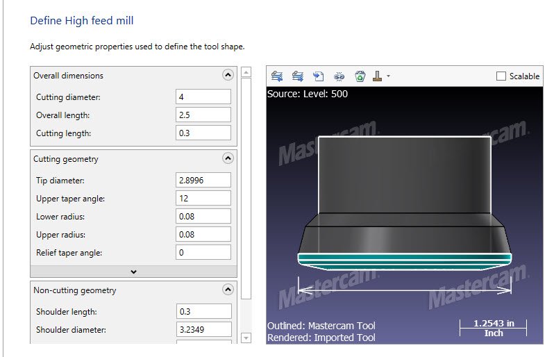
In the example I've attached, I built a tool from an Ingersoll step file, then saved the geometry to a level
and edited it a little
Notice in my example that I've lied in the Cutting length setting..
If I set it correctly the walls in a Verify session look like they've been cut with a .08R button cutter.
The resulting stl file was an unusable 120meg mess.
After tweaking the defining geometry and setting the Cutting Length to .300 my Verify STL's have nice clean walls
and yielded an 18 meg stl instead of a very messy 12o meg file
What was the purpose for the longer than reality cutting length? What other editing did you do, aside from the cutting length?
I noticed you mentioned back feed. Do you find that high feed mills do ok with dynamic toolpaths? I've always leaned more towards contours, and area mill. Toolpaths that make a more "uniform" toolpath. Something about dynamic toolpaths with a high-feed mill makes me feel un-easy. But you guys have far more experience than me, so I'm open to other methods.
-
37 minutes ago, crazy^millman said:
I have used highfeed cutters for almost 20 years and I have always defined them as bull endmills. This process has always worked. Why does it work I did a complete math breakdown of this many years ago and realized yes it leaving a little extra material when defining it this way verses the High Feed way, but when you see major performance hits in some areas of Mastercam using Highfeed Cutters for tool definitions I will stick with the KISS method here.
Sounds good. Thanks Ron. I'm just always worried about hitting one of those little ridges/peaks and going above the radius of the cutter. Probably overthinking it though.
-
11 minutes ago, crazy^millman said:
It is a 1.000 diameter bull endmill with a .094 Radius. You don't need to define the smaller diameter on a bull endmill.
I'm missing something. The green wireframe is a 1" bull endmill with .094rads, and the solid is the step file from Ingersoll. Wont the areas in between be missed material? Or is the step geometry wrong, perhaps?
-
Just now, crazy^millman said:
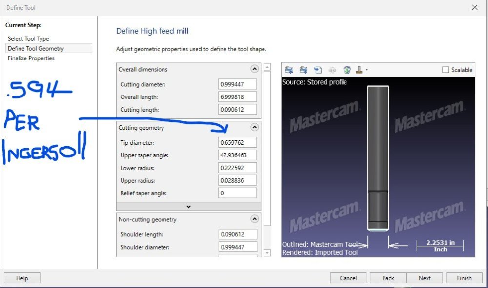
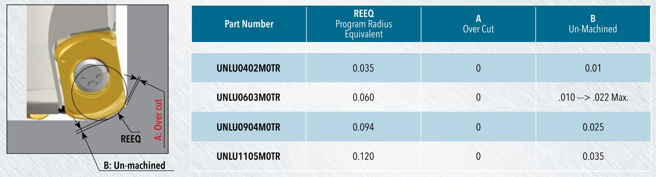
Bull endmill with the recommend radius. Sorry I am still not 100% convinced defining a highfeed cutter is the best process in Mastercam.
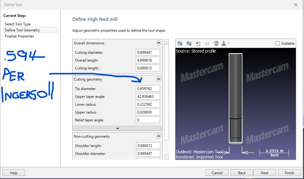
So, how does that work Ron? They give a a recommended program rad of .094", but that would put my actual diamter at .812" when ingersoll claims it to be .594.
I initially had the same thought, however it seems like that would leave unexpected islands and pyramids? If that method works well though, I'll continue defining them as bull endmills, as it's a whole lot simpler.
-
What tool type do you guys use when you build an indexable high feed mill? I tried using the step file from Ingersoll's website, and applying it in a High Feed Mill, but none of the numbers are correct.
https://www.ingersoll-imc.com/product/2906973
-
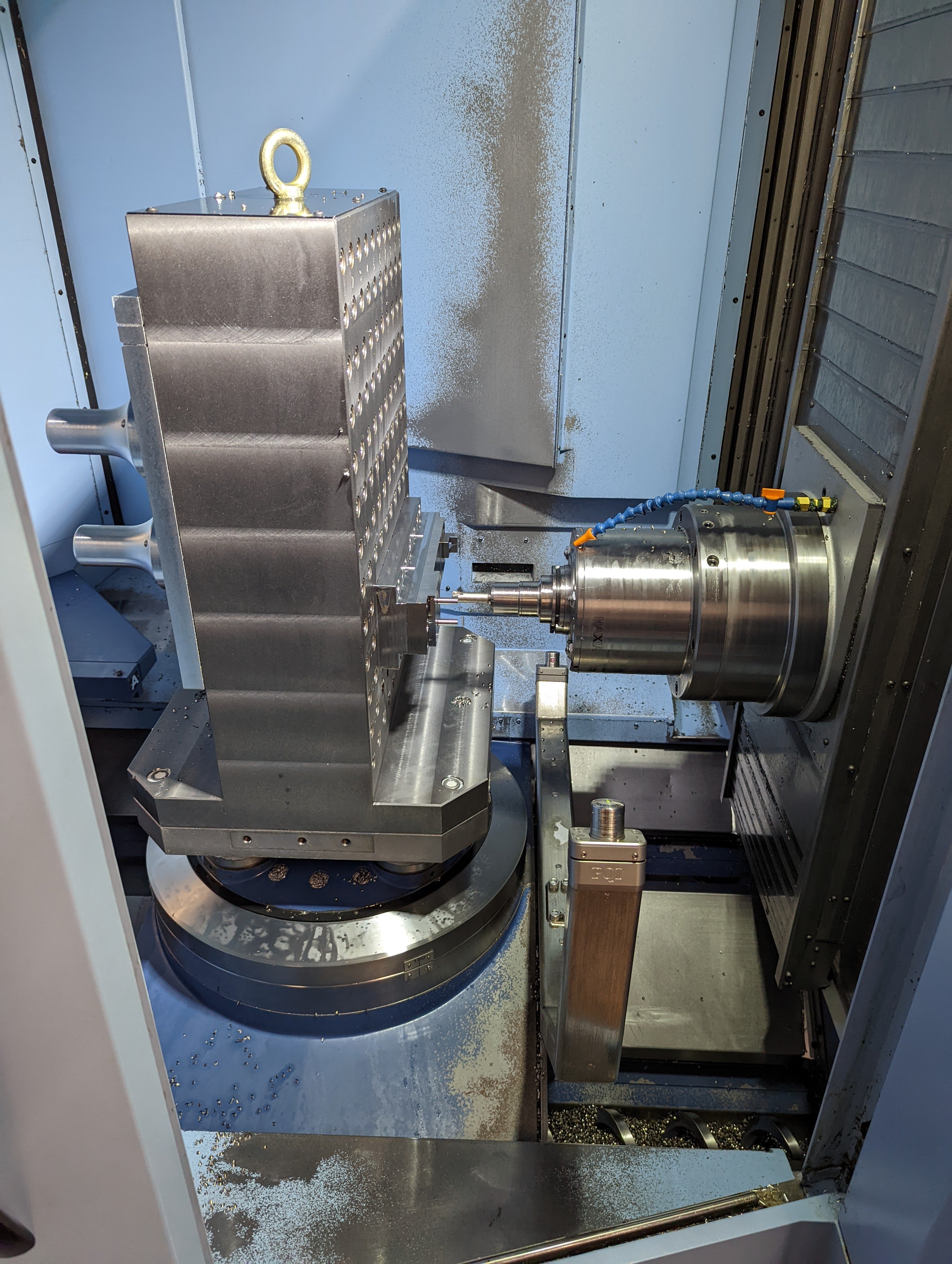
On 8/22/2022 at 9:00 AM, BradyCNC said:
I figure exposed metal on the interior isn't ideal
I don't think I've run a machine that didn't have exposed metal on the inside. Like everyone else mentioned, I wouldn't worry about painting it, it's not going to last. Just get the coolant concentration right.
This is our 2 year old Matsuura.

-
1
-
-
On 8/5/2022 at 10:24 AM, Aaron Eberhard said:
I'd assume (and you know what they say about that..) that NPlus is probably a nACRo or nACo, which from my understanding is basically a nano version of the AlCrN coating. I know that it is harder (as in, cuts & wears better) than traditional AlCrN, but I don't have any real data to back that up.
NPlus is a coating they're using on their 5 flute roughing endmills, designed for aluminum. I wasn't terribly impressed, but maybe my application wasn't the best.
-
8 hours ago, gcode said:
It looks like Ingersoll is imitating Sandvik's Prime line of tooling
You are going to have the build a custom tool which will be difficult as there don't seem to be any models available for download yet
Once you have your custom tools defined the regular turning and facing toolpaths should work
For roughing I'd try Mastercam's Prime module
The Product Bulletin at the link has a lot of info.
After flipping through it, these tools may be a direct replacement for Sandvik Prime tools
It's been about 7 years since Prime came out, maybe their patent has expired ??
Ingersoll isn't always great about putting their models on the website. I'd ask your rep, or check MachiningCloud.
-
 1
1
-
-
13 minutes ago, mwearne said:
Seems to have something to do with the locked rad/diam when using 2022. Unlock and you should be fine. In 2023 it works fine if the lock is on.
Interesting. Good call. That seemed to behave the same way on mine. Thanks!
-
4 minutes ago, JParis said:
Yeah, strange behavior that's not "normal"....typically I'll shut down Mastercam and restart it...
Seems to me at times they are still chasing a memory leak...but what do I know I'm just a programmer ;)
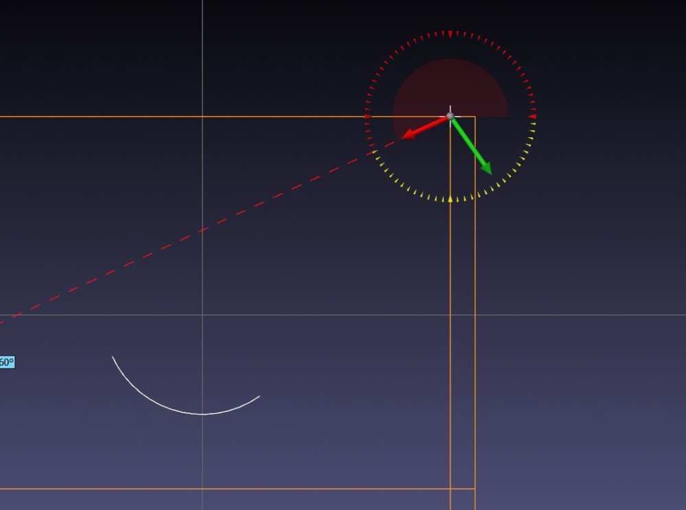
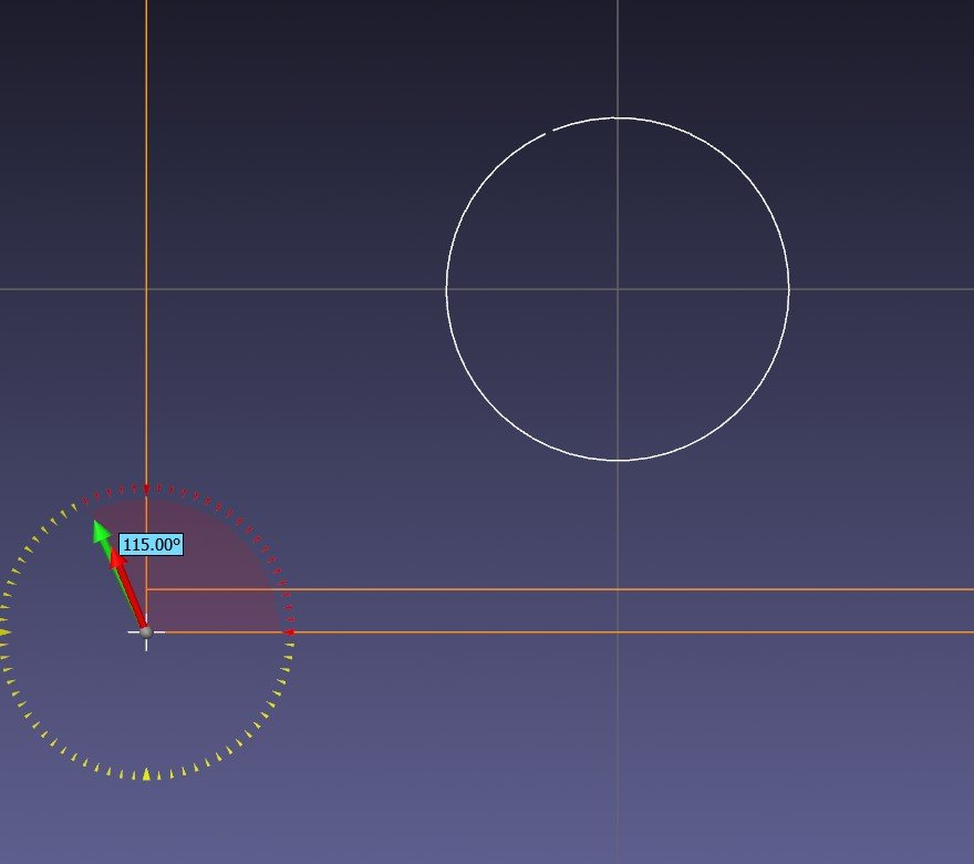
Interesting, I started working on the same thing, and it did it again. Seems it doesn't respect the size either. Radius in the Arc Polar manager was clearly set to .65, and somehow it generated a 1.0 radius. Sounds like this may be something I need to submit to QC
-
7 minutes ago, JParis said:
No doubt that what you are seeing in strange behavior...
I'd restart, might try a new file...just to see if it's something of an anomoly or if it is something that you can reproduce
A restart fixed it, thanks for the obvious suggestion! lol. I do know I've seen it before, so I almost wonder if it's some sort of setting that it getting "stuck" I'll have to try to remember what I did next time it happens.
-
2
-
-
17 minutes ago, JParis said:
Just for grins, are you by chance in 2D? It really shouldn't affect that but I'm curious...
might that geomtry you click be a spline? If so, add a point at the end and try to click the point instyead of the endpoint of that spliine
I was originally in 2D. But in the clip I posted, I was in 3D, and it is in fact a line. I've tried it from all different points in the environment. I have not tried restarting MC, I will now. However, I remember having this problem or something similar in the past as well, and figured I was just doing the wrong series of buttons, and worked around it. I only really noticed it because I started doing the lessons on Streaming Teacher to brush up on some fundamentals, and noticed mine behaved differently than theirs.
-
9 minutes ago, JParis said:
The 1st thing it prompts you for is to click the "Center Point"...I just did it in 2023 and it worked as expected
I'm guessing something in your order
Click >> Create Arc Polar >> Click on the center point >> set arc parameters
Hopefully this works, but that's what I'm doing
-
1 minute ago, AHarrison1 said:
When placing the gnomon have you tried hitting "E" for endpoint or "M" for mid-point?
Just tried it. Same result. I should mention, this function works just fine when I'm just placing a circle.
Actually, seems to work fine in every other function except for arc polar. Tried circle, line, rectangle
-
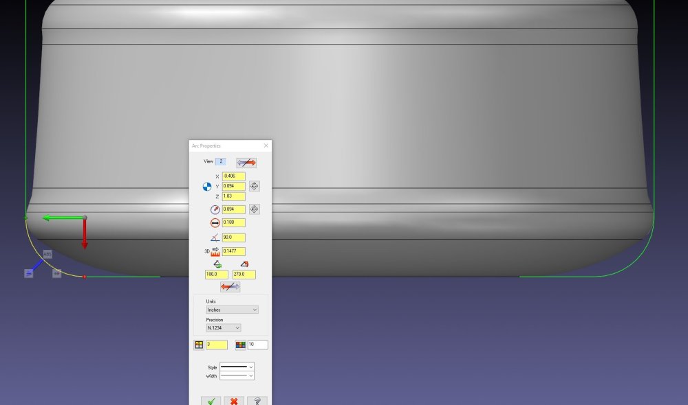
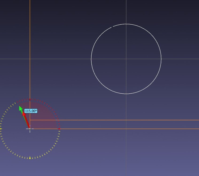
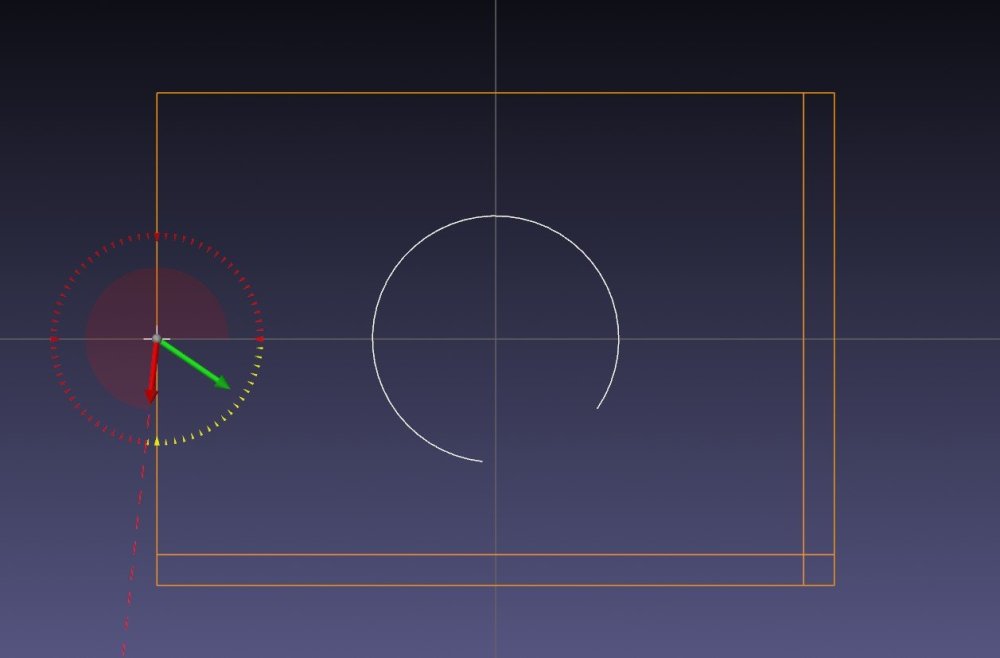
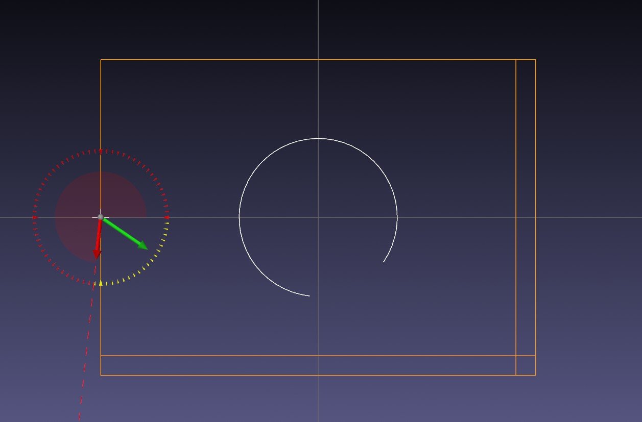
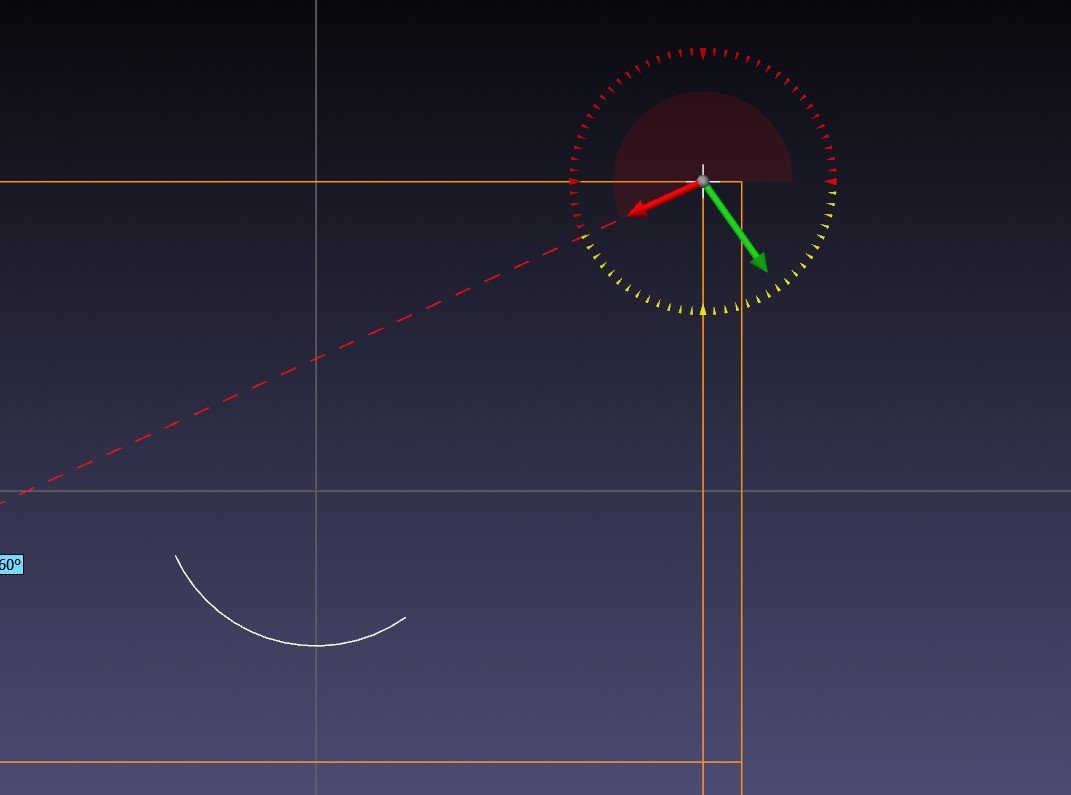
I'm trying to place an arc with Arc Polar, and no matter where I select, it wants to put the arc at the origin. I've tried using the Shift-Relative method, and I've tried all different areas, and no matter what, it goes to center. What the heck am I missing here?
In this screenshot, the arc in white, is the arc currently being created by the gnomon and "clock" at the top right.
-
On 7/15/2022 at 11:10 AM, Rob Dusenbury CAD/CAM CONSULTING said:
These will be true training sessions with material provided, so streaming would not be a valuable option.
Fair enough, wish I was local!!
-
Any chance of adding a streaming option to these sessions. I understand that it may not be a benefit, as most would be outside your service area, but figured I'd ask anyways.
-
8 hours ago, Pete Rimkus from CNC Software Inc. said:
We cannot import 3D data from PDFs (yet).
We can now (in MC2023) import JT files - including any PMI - so I'd recommend that.
Or any of the other formats from which we can import PMI (STEP, NX, Creo, etc.....)
2023 supports all formats without a translator?
-
12 hours ago, Leon82 said:
So matercam will open the pdf but it just displays the print. None of the jt views
There is an extension for a Siemens jt file. I think out customer would have to send us that.
I know we purchased a UG/NX Translator for .prt files. We are using 2022 though. Not entirely sure about 2023. It's nice, but brings in tons of viewsheets, planes, and levels. I usually save it, and use that file strictly for viewing, and reference, and create toolpaths in a separate file.

Organizing a 245 Tool Matrix
in Industrial Forum
Posted
it is a matsuura. Is that done at the controller or at the matrix?